
To see more drawings and photos related to this text, download the PDF.
ADVANTAGES OF RESILIENT HINGE CHECK VALVES OVER TRADITIONAL SWING CHECK VALVES
Check valves are very old. There is evidence that Romans began using check valves to control water flow through their cities between 312 and 270 BC. These were simple “flap” style check valves made of bronze or leather. While these designs were simplistic, the same principle is still used in today’s modern check valves.
By the 1st century BC, Romans had implemented the first force pumps, using dual pistons, each with two check valves, to provide continuous high-pressure water for firefighting. This basic design is still used today for modern hand-operated and powered reciprocating pumps.
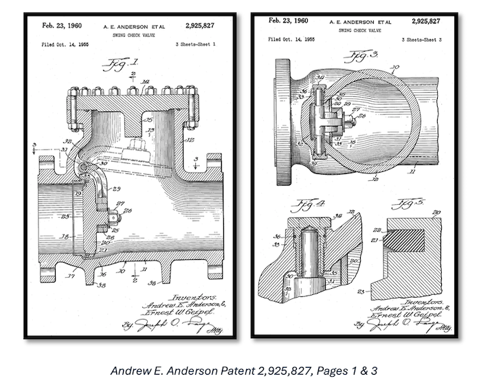
The modern swing check valve design was patented by Andrew E. Anderson for the Crane Company in 1960. It featured a metal hinged disc that swung completely out of the flow path, along with a bolted bonnet that allowed the valve to be serviced without removing it from the pipeline. This design was revolutionary for its time, combining a simple and mechanically reliable method of backflow prevention with a “full waterway” geometry. When fully open, the disc rotates clear of the flow stream, minimizing headloss and allowing near-unrestricted flow.
The addition of the bolted bonnet also marked a major advancement in maintainability, enabling inspection and internal component replacement without cutting the valve out of the line – significantly reducing downtime in municipal and industrial systems.
However, the same features that made the design successful also introduced inherent limitations. The large angular travel of the hinged disc – often approaching 90 degrees – means the valve relies on gravity and reverse flow to close. This results in delayed closure, allowing reverse flow to develop before the valve seals.
This delay makes the swing check valve particularly susceptible to slamming, where the disc closes abruptly under reverse flow conditions and generates pressure surges known as water hammer. These surges can lead to noise, vibration, and potential damage to the valve, piping system, and connected equipment.
In addition, the design is sensitive to flow conditions. Low flow velocities can cause the disc to flutter, while turbulent flow can lead to oscillation, increased wear on hinge components, and premature failure. As a result, although the 1960 design became an industry standard due to its simplicity and low resistance to flow, it often requires supplemental closure devices – such as lever-and-weight systems or oil dashpots – to control disc movement and mitigate these operational challenges.
Today’s design has not changed dramatically from the one patented in 1960, aside from the disc being reshaped to help with clogging issues and closure devices being gradually improved. Swing check closure devices have slowly evolved from early designs established in the 1800s into the modern systems we use today. Closure devices are meant to prevent slamming, which in turn prevents water hammer.
One of two approaches is used to prevent slamming:
1) Close as quickly as possible in systems that cannot tolerate any backflow. Components like positive displacement pumps (gear pumps, diaphragm pumps), centrifugal pumps, and vertical turbine pumps are highly susceptible to damage if any backflow occurs.
2) Slowly allow the disc to swing close in systems that allow backflow. Some components like submersible pumps and axial flow pumps can tolerate a moderate amount of backflow. Some systems will also tolerate moderate backflow, yet still require a check valve to prevent catastrophic, uncontrolled reverse flow. This is also frequently the case for longer pipelines.
Over the last 150 years, four types of manual closure devices have been implemented in the municipal market. Two of these promote fast closing times, and two help slow the closing rate, as discussed in the following table.
|
Device Type |
Era of Adoption |
Key Features |
|
Lever & Weight |
Mid-1800s |
Uses gravity to ensure the valve closes fully and shortens closure time; applied force is adjustable by moving the weight along the arm. Allows minimal to zero backflow. |
| Lever & Spring | Late 1800s |
Ideal for high-speed closure to prevent slamming with zero backflow. |
|
Air Cushion |
Late 1800s |
Basic dampening; uses compressed air to slow the initial swing of the disc and weight, but will not prevent all slamming due to the compressibility of the air. The slower closure rate allows moderate backflow. Caution: This option only prevents slamming in very specific applications. |
|
Oil Controls |
Early 1900s |
The most reliable dampening; uses incompressible oil for precise, slow closure. However, this permits considerable backflow. |
INTRODUCTION OF THE RESILIENT HINGE CHECK VALVE
The swing check valve remained the standard for the water and wastewater industry for decades, until the resilient hinge check valve was first introduced to the market in 1965. This was a revolutionary design, considering it eliminated all internal components of the standard swing check and replaced them with a single piece – a metal disc, fully encapsulated in rubber. This original design has been refined several times to give us the modern resilient hinge check valve we use today.
|
Date |
Milestone/Patent |
Key Innovation |
| 1965 | Introduction | First commercial resilient hinge; replaced metal hinges with a flexible rubber "bridge." |
| 1984 | Jackscrew Integration | Introduction of the Backflow Jackscrew; allowed manually holding the flapper open for system draining/priming. |
| 1986 | US Patent 4,606,372 | 45° angled seat shortened disc travel by 50% to prevent slamming. |
| 2000 | US Patent 6,050,294 | Integrated an internal stainless steel leaf spring for faster closing. |
| 2020s | Reversible Discs | Introduction of KEN-FLEX symmetrical resilient hinge design; allows the disc to be flipped to use a fresh sealing surface, doubling lifespan. |
RESILIENT HINGE VS. SWING CHECK
The modern resilient hinge check valve has been rapidly replacing the standard swing check valve due to several factors.
Simplicity
A resilient hinge check valve only has one moving component. This dramatically reduces the risk of premature component wear due to disc oscillation in low-flow situations. A swing check valve has several components that are prone to premature wear if the flow guidelines for a swing check valve are not adhered to. (Most manufacturers recommend a minimum flow rate of 5 feet per second to hold the disc tight to the body or open stop.)
Fast Closing
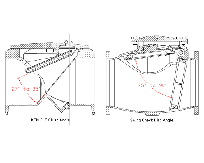
A resilient hinge check valve has a very short travel of 27 to 35 degrees compared to a standard swing check’s disc travel of 75 to 90 degrees. The shorter travel naturally prevents slamming because the disc takes much less time to swing shut when the flow reverses.
Long Lifespan
The KEN-FLEX style resilient hinge is reversible. This allows both a quick fix if the seat is damaged by sharp debris and the long-term benefit of doubling the lifespan of the original valve. It is true that the seat ring on a swing check valve can be replaced without fully rebuilding the disc and hinge mechanism. However, when the disc ring wears out through normal operation, several other internal components typically require replacement as well. In either case, replacing the seat ring requires the swing check valve to be completely disassembled.
No External Components
A resilient hinge check valve is completely maintenance free with no external packing glands like a swing check valve. Packing glands require routine tensioning and rebuilding to prevent leaks around the shaft.
Anti-Clog Design
While both the swing check valve and resilient hinge check valve have a full port design, the resilient hinge check valve body was specifically designed to provide a smooth flowing, anti-clog solution for pipelines containing raw sewage, heavy solids, and fibrous material.
The disc of the traditional swing check valve has been redesigned in recent years to have a domed shape which does help prevent matting or ragging on the disc. (Matting or ragging is where long-strand materials like hair, dental floss, and wipes twist together to form ball or rope-like obstructions, respectively.)
However, the larger body cavity creates a zone of lower fluid velocity and turbulence. In wastewater or sludge applications, solids drop out of suspension in these low-flow pockets, causing heavy sediment build-up. The hinge mechanism(s) and hardware that hang in the flow path are undesirable for applications with solids present. Even with a modern disc that is domed to shed debris, these sharp edges and narrow joints act as an internal anchor. Rags, hair, and stringy materials catch on those points and gradually gather more debris over time.
AN ADVANTAGE OF BOTH DESIGNS: SPRING ASSISTED CLOSURE
In applications where it is critical that the check valve closes before any backflow occurs, such as installing a check valve immediately downstream of a turbine pump, a spring assisted closure device is routinely the recommended solution. Both the swing check and the resilient hinge valves have spring assist options.
A swing check valve can be equipped with a lever & spring closure device to rapidly close the disc before any backflow occurs. A resilient hinge check valve can also be equipped with a spring assisted disc. This is either a stand-alone spring attached to the backside of the disc or a spring with a cover protecting it from collecting media. An example of a fully protected spring closure device is an MPI spring-loaded position indicator.
Note: Some manufacturers utilize a leaf spring design that only pushes the disc partway closed. The most effective way to prevent slamming is with a spring that pushes the disc all the way to the closed position.
IN SOME INSTANCES, THE SWING CHECK VALVE HAS THE ADVANTAGE
Slow Closing
Some applications, such as longer pipelines, require that a check valve close slowly to prevent slam, rather than closing as quickly as possible. In these applications, a swing check valve with an oil control closure device is the best method to accurately control the closing of the disc.
Lay Lengths
The original design of the resilient hinge check valve did not follow AWWA guidelines for lay lengths. This led to several manufacturers producing resilient hinge designs with the same non-standard lay lengths. Fortunately, MPI is now taking steps to standardize the lay lengths of our resilient hinge check valves. This will enable the direct replacement of swing check valves with resilient hinge check valves where an application has been problematic for a standard swing check.
SUMMARY
In many applications, the resilient hinge check valve is a better choice. Either for its non-clogging design, its fast-closing speed, or its low maintenance costs. The resilient hinge check valve has proven itself with decades of successful use in the municipal water industry and should be considered first before choosing a traditional swing check valve.
| Category |
Resilient Hinge Check Valve (KEN-FLEX) |
Traditional Swing Check Valve |
| Design Simplicity |
Single moving part (rubber-encapsulated disc) reduces wear and failure points |
Multiple components (disc, hinge, pin, seals) are prone to wear and misalignment |
| Disc Travel / Closure Speed |
Short travel (27-35°) = fast closure, minimizes reverse flow |
Long travel (75-90°) = delayed closure, allows reverse flow |
| Water Hammer / Slamming | Naturally resistant due to fast close and short stroke |
Highly susceptible; often requires external damping devices |
| Clogging Resistance |
Smooth body and encapsulated disc minimize debris buildup; ideal for wastewater/solids |
Hinge hardware & internal cavities trap debris; prone to ragging and sediment buildup |
| Maintenance Requirements |
Maintenance-free design; no external packing or adjustments |
Requires maintenance (packing glands, hinge components, closure devices) |
| Durability / Lifespan |
Reversible disc doubles usable life; fewer wear components |
Wear affects multiple parts; rebuild typically required for full restoration |
| Application Strength |
Best for wastewater, solids, frequent cycling, and low maintenance systems |
Better where controlled slow closure is needed (e.g., in long pipelines, using oil controls) |
See our white paper “Understanding Swing Check Valves” for more information.